Views: 59470 Author: Site Editor Publish Time: 2024-08-30 Origin: Site


Calculating the correct flat pattern layout is crucial to getting a good quality finished part from your press brake. Yet, many CAD and CNC programmers have no idea how to calculate the required values. Years ago, the real experts created cheat sheets and tacked them to the wall. They only taught the new apprentice how to apply the results shown on the cheat sheet, not how to calculate the numbers. Well, now those experts have retired and it's time for a new generation to learn the right way to calculate the correct flat pattern layout.
Calculating the flat pattern length from the 3D part really isn’t that difficult. Although you may find several different formulas that claim to calculate the Bend Allowance (See Bending Definitions), they usually are the same formula, only simplified by filling in the angle or a K-factor. Oh, and yes, you do need to know the K-factor to calculate the Bend Allowance.

Let’s start with a simple L bracket. The picture shows that the legs of the bracket are 2” and 3”. The material thickness is 0.125”, the inside radius is 0.250”, and the angle of bend is 90 degrees. The flat length is the total of the flat portion of both flanges plus the length through the arc of the bend area. But, do you calculate that on the inside of the material or the outside? Neither! This is where the K-factor comes into play. The K-factor is the percentage of the material thickness where there is no stretching or compressing of the material, for example, the neutral axis. For this simple L bracket, I will use a K-factor of 0.42.

The formula (See Bending Formulas) is:
Bend Allowance = Angle * (π / 180) * (Radius + K-factor * Thickness).
Plugging in our numbers, we have: Bend Allowance = 90 * (π / 180) * (0.250 + 0.42 * 0.125) = 0.475"
So the flat pattern length is 1.625” + 2.625” + 0.475" which is equal to 4.725". So if you add up the flat length of all the flanges and add one Bend Allowance for each bend area you have the correct flat length of the part.
But look at the drawing. That is not how we normally dimension a sheet metal part. The dimensions are usually to the intersection of the flanges or the Mold Line. This means that we have to subtract two times the material thickness plus the bend radius (also known as the Setback) for each bend area. For this set of dimensions, it would be easier to calculate the Bend Compensation value. The Bend Compensation value lets you add up the length of each flange using the Mold Line dimensions and then add one Bend Compensation per bend area to the total. It is -0.275, a negative number, which means you will subtract this amount from the total of the flange lengths, 5”, to get 4.725".
Bend Allowance = Angle * (π / 180) * (Radius + K-factor * Thickness)
Bend Compensation = Bend Allowance – (2 * Set Back)
Inside Set Back = tan (Angle / 2) * Radius Outside
Set Back = tan (Angle / 2) * (Radius + Thickness)

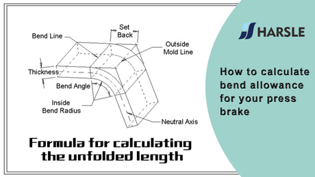
Bend Allowance – The length of the arc through the bend area at the neutral axis.
Bend Angle – The included angle of the arc formed by the bending operation.
Bend Compensation – The amount by which the material is stretched or compressed by the bending operation. All stretch or compression is assumed to occur in the bend area.
Bend Lines – The straight lines on the inside and outside surfaces of the material where the flange boundary meets the bend area.
Inside Bend Radius – The radius of the arc on the inside surface of the bend area.
K-factor – Defines the location of the neutral axis. It is measured as the distance from the inside of the material to the neutral axis divided by the material thickness.
Mold Lines – For bends of less than 180 degrees, the mold lines are the straight lines where the surfaces of the flange bounding the bend area intersect. This occurs on both the inside and outside surfaces of the bend.
Neutral Axis – Looking at the cross section of the bend, the neutral axis is the theoretical location at which the material is neither compressed nor stretched.
Set Back - For bends of less than 180 degrees, the set back is the distance from the bend lines to the mold line.
To my knowledge, there is not a formula for calculating the k-factor. Oh, I am certain somewhere some mathematical engineer has a formula. But it is most likely too complex for most of us to understand or be able to use.
The k-factor is the percentage of the material thickness where there is no stretching or compressing of the material in the bend area. Thus, the neutral axis!
The harder the material, the less compression there is on the inside of the bend. Therefore, more stretching on the outside and the neutral axis moves toward the inside of the bend. Softer materials allow more compression on the inside and the neutral axis remains closer to the center of the material thickness.
Bend radius has a similar effect. The smaller the bend radius, the more need for compression and the neutral axis moves toward the inside of the bend. On a larger radius. the neutral axis remains near the center of the material thickness.

In order to help you master the calculation formula of unfolded length of bending more simply and quickly, we listed four common coefficient tables for you, illustrated sixteen calculation formulas of unfolded length of bending, and we also take some examples for better understanding. I hope that the following contents can help you practically. If you have any questions, Please feel free to contact us.


A, B--- bending length of workpiece
P'---bending coefficient of edge bending (bending factor: one factor minus one bend)
R--- bend and fillet (generally plate thickness)
T--- material thickness
The Expanded length L=A+B-P', which is L=25+65-5.5=84.5
According to Table 1, the plate thickness is 3, the lower die is V25, and the bending coefficient is 5.5
Note: According to Table 1, different bending coefficients of lower dies and different plate thicknesses are different.

A(A1), B--- bending length of workpiece
P'---bending coefficient of edge bending (bending factor: one factor minus one bend)
R--- bend and fillet (generally plate thickness)
T--- material thickness
The Expanded length L=A+T+B-2*P', which is L=50+2+50-2*3.4=95.2
According to Table 1, the plate thickness is 2, the lower die is V12, and the bending coefficient is 3.4
Note: According to Table 1, different bending coefficients of lower dies and different plate thicknesses are different.

A(A1), B (B1)-bending length of workpiece
P'---bending coefficient of edge bending (bending factor: one factor minus one bend)
R--- bend and fillet (generally plate thickness)
T--- material thickness
The Expanded length L=A+T+B+T-3*P', which is L=50+2+90+2-3*3.4=133.8
According to Table 1, the plate thickness is 2, the lower die is V12, and the bending coefficient is 3.4
Note: According to Table 1, different bending coefficients of lower dies and different plate thicknesses are different.

A, B (B1)-bending length of workpiece
P'---bending coefficient of edge bending (bending factor: one factor minus one bend)
R--- bend and fillet (generally plate thickness)
T--- material thickness
The Expanded length L=A+A+B+T+T-4*P', which is l = 25+25+100+1.5+1.5-4 * 2.8 = 141.8
According to Table 1, the plate thickness is 1.5, the lower die is V12, and the bending coefficient is 2.8
Note: According to Table 1, different bending coefficients of lower dies and different plate thicknesses are different.

A(A1), B (B1)-bending length of workpiece
P'---bending coefficient of edge bending (bending factor: one factor minus one bend)
R--- bend and fillet (generally plate thickness)
T--- material thickness
The Expand length L=A+T+A+T+B+B1+B1-6*P'
which is l = 50+1.5+50+1.5+150+20+20-6 * 2.8 = 276.2
According to Table 1, the plate thickness is 1.5, the lower die is V12, and the bending coefficient is 2.8
Note: According to Table 1, different bending coefficients of lower dies and different plate thicknesses are different.

A, B--- bending length of workpiece
P'---flattening fillet bending coefficient
R--- bend and fillet (generally plate thickness)
T--- material thickness
The Expanded length L=A+B-P', which is L=25+65-1=89
According to Table 2, the plate thickness is 2, the lower die is V12, and the bending factor is half of the plate thickness
Note: According to Table 2, the selection of different lower die has different bending coefficients and different plate thicknesses.

A, B--- bending length of workpiece
P1--- bending coefficient of inner corner
P2--- bending coefficient of external bending angle
R--- bend and fillet (generally plate thickness)
T--- material thickness
The Expanded length L1=(A-1.5) +(B-1.5)-P1, which is L1= (65-1.5) +(25-1.5)-3.2=83.8
L2=A+B-P2, which is L2=65+25-4.1=85.9
L=L1+L2-T/2, which is L=83.8+85.9-0.75=168.95
According to Table 2, the plate thickness is 1.5, the lower die is V12, the inner corner bending coefficient is 3.2, the outer corner bending coefficient is 4.1, and the 180 bending coefficient is 0.75.
Note: According to Table 2, different bending coefficients of lower dies and different plate thicknesses are different.

A, A1, A2, B1, B2, L, L1, L2, L3--- bending length of workpiece
P1--- bending coefficient of inner corner
P2--- bending coefficient of external bending angle
R--- bend and fillet (generally plate thickness)
T--- material thickness
The Expanded length L1=(A1-T) +(B2-T)-P1 which is L1= (35-2) +(34-2)-3.7=61.3
L2=(B1-T) +(A2-T)-P1, which is L2= (50-2) +(34-2)-3.7=76.3
L3=A+B1+B2-2*P2, which is L3=70+35+50-2*4.6+145.8
L=L1+L2+L3-2*P3, which is L=61.3+75.3+145.8-2*1=280.4
According to Table 2, the plate thickness is 2, the lower die is V12, the inner corner bending coefficient is 3.7, the outer corner bending coefficient is 4.6, and the 90-bending coefficient is 1.
Note: According to Table 2, different bending coefficients of lower dies and different plate thicknesses are different.
Diagram and calculation formula of step bending

A, B--- bending length of workpiece
R--- bend and fillet (generally plate thickness)
T--- material thickness
Unfolded length L=A+1
Note: When the step is equal to the thickness of two plates, add 0.5 for each step and 1 for each step.

A(A1), B (B1)-bending length of workpiece
P'---bending coefficient of edge bending (bending factor: one factor minus one bend)
R---bend and fillet (generally plate thickness)
T--- material thickness
The Expand length L=(A-T) +(B-T)-P', which is L= (66-1) +(26-1)-2=65+25-2=88
According to Table 3, the plate thickness is 2, the lower die is V12, and the 60 bending coefficient is 2
Note: According to Table 3, the neutral layer is selected as the bending length and width.

A (A1, A2, A3, A4), B--- bending length of workpiece
P--- bending factor of 135 bending angles
R--- bend and fillet (generally plate thickness)
T--- material thickness
The Expand length L = A1+A2+A3+A2+A4-P-P.
Note: the same pressure step bending only needs to reduce two coefficients
According to Table 3: the plate thickness is 2, the lower die is V12, and the bending coefficient at 135 is 1.1.

A (A1, A2), B (B1, B2)-bending length of workpiece
P1---120° bending coefficient
P2---145° bending coefficient
P3---90° bending coefficient
R--- bend and fillet (generally plate thickness)
T--- material thickness
Note: if the graphic size is marked on the shape, the shape size should Be converted to the neutral layer size when calculating the unfolding length;
The Expand length L=A11+B11+B21+A21-P1-P2-P3, which is l = 80+50+103+70-1.7-0.7-3.4 = 297.2
According to Table 3: the plate thickness is 2, the lower die is V12, the 120 bending coefficient is 1.7, the 145 bending coefficient is 0.7, and the 90-bending coefficient is 3.4
Note: According to Table 3, different bending coefficients of lower dies and different plate thicknesses are different.

A, B, C--- length, width and height of workpiece bending edge
P--- bending coefficient
R--- bend and fillet (generally plate thickness)
H(H1), l (L1)-the unfolded length of each side
T--- material thickness
D--- bending process clearance (generally 0~0.5)
The Expanded length L1=A, which is L1=27
L=A+C-P, which is L=27+9-3.4=32.6
H1=B-T-D, which is H1=22-2-0.2=19.8. Note: D is 0.2.
H=B+C-P, which is H=22+9-3.4=27.6
According to Table 1: the plate thickness is 2, the lower die is V12 and the bending coefficient is 3.4
Note: According to Table 1, different bending coefficients of lower dies and different plate thicknesses are different.

A, B, C--- length, width and height of workpiece bending edge
H(H1), L (L1)-the unfolded length of each side
P---90° bending coefficient P1---30° bending coefficient
R--- bend and fillet (generally plate thickness)
T--- material thickness
D--- bending process clearance (generally 0~0.5)
The Expanded length L1=B-T-D, which is L1=20-1.5-0.2=18.3
L=B+C1+C2-P-P1, which is L=20+12+8.9-2.8-0.5=37.6
H1=C1+A-P-D, which is H1=12+35-2.8-0.2=44. Note: D is 0.2.
H=A+C-P, which is H=35+20-2.8=52.2
According to Table 1: the plate thickness is 1.5, the lower die is V12, the bending coefficient is 2.8, and the 30-bending coefficient is 0.5
Note: According to Table 1, different bending coefficients of lower dies and different plate thicknesses are different.

A, B, C--- length, width and height of workpiece bending edge
H(H1), L (L1)-the unfolded length of each side
P--- bending coefficient
R--- bend and fillet (generally plate thickness)
T--- material thickness
D--- bending process clearance (generally 0~0.5)
The Expanded length H1=B-B1-D, which is H1=50-12-0.3=37.7. Note: D is 0.2.
H2=B-T-D which is H2=50-2.5-0.3=47.2
H=B+C+B1-2*P, which is H=50+47+12-2*4.5=100
L1=A+C-T-D-P, which is L1=55+47-2.5-0.3-4.5=94.7
L=A+C+B2-2*P, which is L=55+47+12-2*4.5=105
According to Table 1: the plate thickness is 1.5, the lower die is V16 and the bending coefficient is 4.5
Note: According to Table 1, different bending coefficients of lower dies and different plate thicknesses are different.

 English
 Pусский